


Key takeaways:
- Creo 9 release strengthens support for designer productivity with added surface controls and editing.
- PTC introduces Multiphysics simulation for thermal/structural from within Creo 9.
- Users can now build their own additive manufacturing support structures in Creo.
The Launch
In May, 2022, PTC launched Creo 9 with a complimentary webinar showcasing the solution’s new enhancements.[1] Mr. Paul Sagar, Vice President of CAD Product Management, noted that improvements centered in five areas of the product:
- Usability and Productivity
- Design for Ergonomics
- Model-Based Definition and Detailing
- Generative Design and Simulation
- Additive and Subtractive Manufacturing
Usability and Productivity
Mr. Sagar explained that there are times when the designer needs to split a model surface to perform subsequent operations. The need may be to apply a specific surface finish to only a portion of the surface, or the designer may need to apply a load or constraint to a specific model location. PTC has introduced a new Divide Surface command to split a surface into different regions separated either by a curve or projected sketch―see Figure 1.
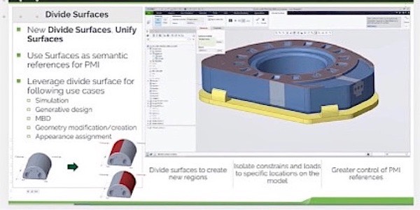
Figure 1―Creo 9’s Divide Surface
(Courtesy of PTC)
The split surfaces can have different semantic references for PMI. The reverse operation of Unify Surface is also included to combine sufaces. CIMdata agrees that these operations will provide users the flexibility they require in many diverse design situations.
In the previous release PTC introduced the concept of a Design Items Folder.to better capture and document design intent independent of the history tree. In Creo 9, the capability has been extended to allow users to place features into custom groups. The user can organize design items to help document design intent with flexibility and freedom.
Creo 9 supports an enhanced parent/child viewer. The user can now dynamically show the parent or the children of a selected feature. CIMdata sees this as a strong tool in a user’s arsenal when they need to explore the structure of a model.
Users can now generate a geodesic curve (Figure 2) on a surface by specifying a point and an angular direction. The curve path follows the shortest distance along the surface.
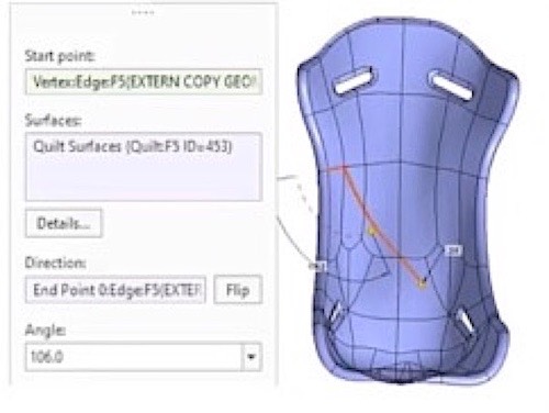
Figure 2―Creo 9’s Geodesic Curve Generation
(Courtesy of PTC)
Creo 9 also introduces new sculpting brushes for free style surface modeling allowing the user to control the shape of the sub-divisional mesh. See Figure 3.
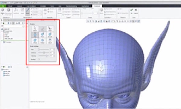
Figure 3―New Brush Tools for Free Style Surfacing
(Courtesy of PTC)
Design for Ergonomics
In Creo 9, a new Manikin editor allows a company to create custom manikin populations for their use in testing human interaction with their virtual design models. In addition, PTC has included usability enhancements (Figure 4) for better control over positioning a manikin in the design. The user can now identify and analyze gaps between actual and intended positions.
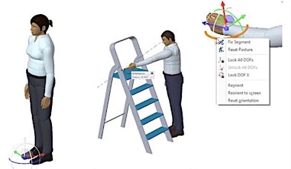
Figure 4―Creo 9’s Enhanced Manikin Manipulation
(Courtesy of PTC)
A new Vision Field Analysis capability shown in Figure 5 allows the user to analyze a manikin’s line of sight and field of view. This capability helps ensure quality, safety, and adherence to visibility standards. CIMdata considers this tool useful in many design scenarios and helps avoid late minute design changes once a physical prototype is built.
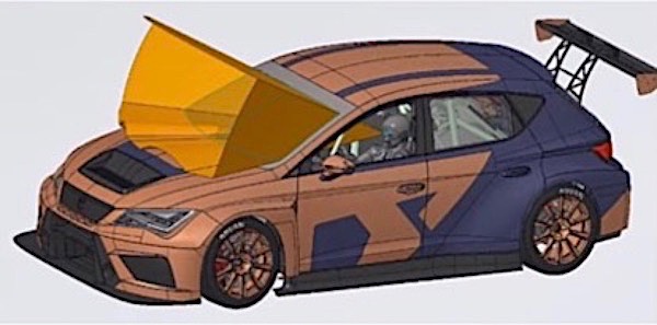
Figure 5―Creo’s New Vision Field Analysis Capability
(Courtesy of PTC)
Generative Design and Simulation
In Creo 9, PTC continues to build on their partnership with ANSYS broadening use cases for simulation-driven design. In what CIMdata believes is a major step, PTC takes their first step toward Multiphysics simulation with thermal stress computation in Creo Simulation Live, shown in Figure 6.
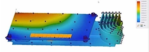
Figure 6―Multiphysics Simulation with Thermal Stress
(Courtesy of PTC)
CIMdata welcomes this step forward for Creo and believes users will appreciate this move toward Multiphysics simulation. In addition, Creo Simulate Live can now simulate the complex geometry of formula-driven lattices opening opportunities to perform fluid simulation on those lattices.
Often users want to evaluate using different input values for their simulations. The introduction of multiple projects in Creo 9 caught the eye of CIMdata. Users can now use the same model geometry and constraints, while varying parameters between projects to evaluate multiple design choices.
Additive and Subtractive Manufacturing
In release 9, users can now leverage the full geometric power of Creo to build their own supports and identify them as support structures for additive manufacturing. This allows the assignment of different printing parameters for supports versus actual part geometry. On the subtractive machining side of manufacturing, Creo 9 introduces full 5 -axis geodesic finish toolpaths which parallel the generation of geodesic curves cited above under Useability and Productivity.
Summary
While PTC included many more enhancements in Creo release 9, CIMdata chose to highlight those discussed in this Commentary based on a belief that they will impact a majority of Creo user companies. CIMdata believes that PTC has focused their improvements in the proper areas, those that are most useful to end users and continues to enhance these as well as other areas.
[1]Research for this commentary was partially supported by PTC.